Distance, Attitude, and Relative 3D Measurement
The SPD1200ZG combines compact 905 nm pulsed laser ranging with integrated inertial angle sensing for OEM systems that need distance, attitude, and relative three-dimensional point-to-point measurement in one lightweight module.
It supports single and continuous ranging, configurable angle reporting, and UART-TTL communication for host integration.
Nominal body dimensions are 7.2 × 14.7 × 22.3 mm and weight is no more than 5 g; the complete installation envelope is governed by the current mechanical drawing.
01
SPAD-based pulsed ranging
905 ± 5 nm direct time-of-flight ranging with single-photon reception for weak optical returns.
02
0.1–1200 m specified range
Rated with visibility ≥10 km, humidity ≤60%, and a building target.
03
Integrated six-axis inertial sensing
Configurable roll, pitch, and relative yaw/heading reporting for angle-enabled builds.
04
Relative 3D point-to-point measurement
Combines local range and angle information for target-point coordinates and spatial separation.
05
Compact OEM package
Nominal body size 7.2 × 14.7 × 22.3 mm, 6061 aluminum-alloy housing, and weight ≤5 g.
06
Flexible host integration
UART-TTL communication, 115200 bps default baud rate, and a 2–10 Hz measurement update rate.
TECHNICAL DATA
SPD1200ZG Specifications
Read each performance value with its stated target, environmental, operating, and installation conditions.
Optical and ranging
| Parameter | Value | Conditions / notes |
| Laser wavelength |
905 ± 5 nm |
— |
| Beam divergence |
<6 mrad; small beam spot |
— |
| Optical element |
Aspheric lens |
— |
| Receiver aperture |
Ø6.5 mm |
— |
| Measurement range |
0.1–1200 m |
Visibility ≥10 km; humidity ≤60%; building target |
| Ranging accuracy |
±0.5 m at d ≤100 m; ±(0.5 m + 0.0007d) for 100 m < d <1200 m |
— |
| Measurement update rate |
2–10 Hz |
— |
| Measurement success rate |
≥98% |
— |
| False alarm rate |
≤1% |
— |
| Laser safety class |
IEC Class 1 |
— |
Electrical and environmental
| Parameter | Value | Conditions / notes |
| Communication interface |
UART-TTL; customizable |
— |
| Default baud rate |
115200 bps |
— |
| Supply voltage |
3.3–5 V |
— |
| Startup time |
≤200 ms |
— |
| Peak startup current |
≤200 mA |
— |
| Standby power consumption |
≤0.3 W |
— |
| Average power consumption |
≤0.7 W |
— |
| Operating temperature |
−20 to +60 °C |
— |
| Storage temperature |
−30 to +70 °C |
— |
| Ingress protection |
IP67 within the lens cavity |
— |
Mechanical
| Parameter | Value | Conditions / notes |
| Nominal module body |
7.2 × 14.7 × 22.3 mm; rectangular |
The complete installation envelope includes protruding features; use the current mechanical drawing. |
| Housing material |
6061 aluminum alloy |
— |
| Weight |
≤5 g |
— |
| Width across protruding features shown in drawing |
9.8 ± 0.2 mm |
— |
| Core width shown in drawing |
7.2 +0.01/−0.03 mm |
— |
| Height shown in drawing |
14.7 +0.01/−0.03 mm |
— |
| Axial dimensions shown in drawing |
22.3 ± 0.1 mm and 21.3 mm |
— |
| Mounting features shown in drawing |
2 × M1.6; 5.2 ± 0.02 mm spacing feature |
— |
| Optical features shown in drawing |
2 × Ø6.5; 7.5 ± 0.01 mm spacing feature |
— |
| Center-of-gravity coordinates shown in drawing |
7.1, 4.8, 10.7 |
— |
Inertial measurement
| Parameter | Value | Conditions / notes |
| Roll range, X axis |
±180° |
— |
| Pitch range, Y axis |
±90° |
— |
| Yaw range, Z axis |
±180° |
— |
| X/Y tilt accuracy |
0.3° |
— |
| Z-axis heading accuracy |
≤0.75° within a 10 s dynamic measurement interval |
Integration error accumulates during motion; this is relative heading, not an absolute north reference. |
| Axis orientation |
Y axis points toward the lenses |
— |
3D point-to-point — radial error
| Parameter | Value | Conditions / notes |
| d ≤500 m |
±1 m |
Distance variable d follows the product specification. |
| 500 m < d <1200 m |
±(1 m + 0.001d) |
Distance variable d follows the product specification. |
3D point-to-point — static maximum absolute error
| Parameter | Value | Conditions / notes |
| <100 m |
≤1 m |
— |
| 100–500 m |
≤3 m |
— |
| 500–1000 m |
≤5 m |
— |
3D point-to-point — dynamic maximum absolute error
| Parameter | Value | Conditions / notes |
| <50 m |
≤1 m |
— |
| 50–100 m |
≤3 m |
— |
| 100–500 m |
≤6 m |
— |
| 500–1000 m |
≤10 m |
— |
HOW IT WORKS
Pulsed Time of Flight and SPAD Reception
Pulsed Time-of-Flight Ranging
The module transmits a short optical pulse and detects light reflected from the target. If the measured round-trip transit time is Δt, the geometric one-way range is R = cΔt / 2. The factor of two accounts for the outbound and return paths.
Timing resolution, pulse width, receiver bandwidth, target reflectivity, incidence angle, background illumination, and beam divergence influence practical ranging performance. [1]
R = c × Δt / 2R: one-way geometric distance · c: speed of light along the path · Δt: measured round-trip transit time
SPAD-Based Single-Photon Reception
This SPD1200ZG configuration uses SPAD-based single-photon reception. A single-photon avalanche diode can register individual photon events.
In direct-ToF systems generally, repeated photon detections may be organized in time bins so that a return concentrated around one delay can be distinguished from background detections. Ambient illumination, detector dead time, pile-up, and finite timing resources are recognized constraints. [2] [3]
The standard customer interface reports processed measurements; it does not claim access to raw photon timing data or a particular internal processing algorithm.
INERTIAL + 3D
Six-Axis Inertial Measurement Explained
A conventional six-axis IMU comprises three orthogonal gyroscope angular-rate channels and three orthogonal accelerometer specific-force channels. Six-axis describes six sensing channels, not six independent rotational axes. [6]
Angle reporting is configurable and does not imply that the standard customer interface exposes all six raw sensor channels. Available outputs are defined by the configuration-matched interface protocol.
For a fixed single-axis rotation, the conceptual relationship is θ(t) = θ₀ + ∫ω(t)dt. Angular-rate bias and noise create accumulated angle drift. Three-axis attitude estimation requires an appropriate coordinate convention. [5]
| Measurement | Rating |
| Roll |
±180° about the X axis |
| Pitch |
±90° about the Y axis |
| Relative yaw / heading |
±180° about the Z axis |
| X/Y tilt accuracy |
0.3° |
| Z-axis heading accuracy |
≤0.75° within a 10 s dynamic measurement interval |
Integration error accumulates during motion. This is relative heading, not an absolute north-referenced compass specification.
Coordinate Convention
Use the current manual's X/Y/Z convention when interpreting angle-enabled output.
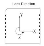 Coordinate AxesThe Y axis points toward the lenses. Use the coordinate convention in the current user manual.