Compact Ranging with Laser Indication
SPD1200N3 combines a 905 nm ranging laser and single-photon receiver with a laser-indication function. ERDI confirms that its ranging laser and receiver are shared with SPD1200ZG; the model-specific ranging limits, mechanical design and indication functions must still be evaluated separately.
SPD1200ZG provides inertial orientation information. SPD1200N3 provides laser indication instead; this is not a claim of a six-axis IMU, compass heading or 3D point-to-point measurement for N3.
The N3 specification states a 3–1000 m range on a building target under visibility of at least 10 km and humidity no greater than 60%. The nominal rectangular body is 14 × 18 × 22.3 mm and weighs no more than 6 g.
MODEL-LEVEL DATA
Detailed SPD1200N3 Specifications
Read the values together with their source conditions. Literature and related-model data do not replace these ratings.
| Parameter | Value | Source condition |
| Laser wavelength |
905 ± 5 nm |
Ranging emitter; not the indication-laser wavelength |
| Beam divergence |
<6 mrad |
See the controlled model document |
| Optical element |
Aspheric lens |
See the controlled model document |
| Receive / transmit aperture |
Ø6.5 mm |
See the controlled model document |
| Measurement range |
3–1000 m |
Building target; visibility ≥10 km; humidity ≤60% |
| Ranging accuracy |
±0.5 m at d ≤100 m; ±(0.5 m + 0.00075d) for 100 m < d <1000 m |
d is distance in meters; no additional endpoint accuracy inferred |
| Measurement update rate |
2.5–15 Hz |
Varies with distance; not the laser pulse repetition rate |
| Measurement success rate |
≥98% |
Source rating; validate representative targets and conditions |
| False alarm rate |
≤1% |
Source rating; not a universal field guarantee |
| Communication interface |
UART, 3.3 V TTL; customizable |
See the controlled model document |
| Default baud rate |
115200 bps |
See the controlled model document |
| Supply voltage |
DC 3.3–5 V |
Does not imply 5 V tolerance on serial inputs |
| Startup time |
≤200 ms |
See the controlled model document |
| Instantaneous startup current |
Approximately 200 mA |
See the controlled model document |
| Standby power consumption |
≤0.3 W |
See the controlled model document |
| Average power consumption |
≤0.5 W |
See the controlled model document |
| Operating temperature |
−20 to +60 °C |
See the controlled model document |
| Storage temperature |
−30 to +70 °C |
See the controlled model document |
| Ingress protection |
IP67 within the lens cavity only |
Not a whole-module or finished-equipment rating |
| Laser safety class |
IEC Class 1 stated in the ranging specification |
Do not extend this rating to indication/alignment modes or the finished system without confirmation |
| Nominal body dimensions / material |
14 × 18 × 22.3 mm; rectangular; 6061 aluminum alloy |
Use the controlled mechanical drawing and tolerances |
| Weight |
≤6 g |
See the controlled model document |
Functional Description
Single measurement initiates one target-distance measurement and returns the result over the serial interface; the source describes repeated acquisition for low-reflectivity targets until a stable reading is obtained.
Continuous measurement repeatedly reports target distance at a distance-dependent 2.5–15 Hz update rate.
The serial baud rate can be configured to match host requirements. Use firmware-matched packet definitions and test command, response, checksum and failure handling on the ordered configuration.
Electrical Interface Definition
| Pin | Signal | Function |
| 1 |
GND |
Power-supply ground |
| 2 |
VCC |
Positive supply input |
| 3 |
IO (reserved) |
Reserved for expansion |
| 4 |
TXD |
Signal output: module to host |
| 5 |
RXD |
Signal input: host to module |
| 6 |
SW-SHOT |
Function enable, active high (>1.2 V); confirm supplied configuration before wiring |
Check the numbered connector view before wiring. Supply voltage and UART input tolerance are different electrical limits.
Mechanical Dimension Drawing and Electrical Interface Diagram
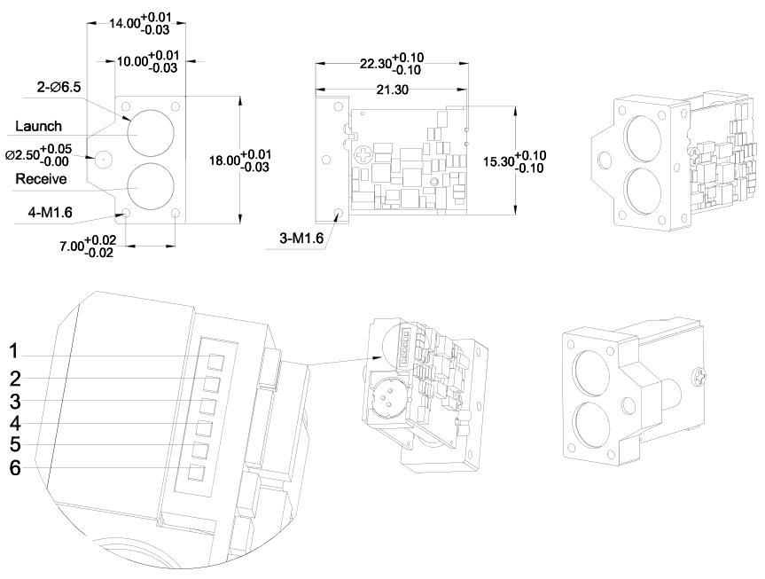 Mechanical dimensions and six-pin electrical interfaceDrawing extracted without generative editing from the N3 source. The nominal body is 14 × 18 × 22.3 mm; use the drawing tolerances, datum and pin orientation. “Launch” identifies the transmit aperture and “Receive” the receive aperture.