Meet the LRF3000A1
The LRF3000A1 extends this selection to a 3000 m range class while keeping a TTL-level UART host interface. The maximum-range condition is explicit: a building target with 70% reflectivity, clear weather, and visibility of at least 4 km.
The minimum-range entry is 1 m on a 90%-reflectivity whiteboard. These minimum and maximum figures use different targets; they should not be combined into an unconditional all-target range guarantee.
Normal mode provides a 3–10 Hz adaptive update rate, while long-range mode is specified at 1–10 Hz. The electrical specification allows 3.3–5 V DC with supply ripple below 0.1 V.
01
Explicit long-range conditions
≥3000 m on a 70%-reflectivity building in clear weather with visibility ≥4 km.
02
Two measurement modes
3–10 Hz normal mode and 1–10 Hz long-range mode; both are adaptive.
03
Defined UART interface
3.3 V TTL-level UART; 115200 bps default with a documented 9600 bps setting.
04
Power and packaging
3.3–5 V DC with <0.1 V ripple and a 12 ± 0.5 g specified mass.
TECHNICAL DATA
LRF3000A1 Specifications
Read performance values with their target and test conditions. The linked user manual provides the complete mechanical, electrical, and communication details.
| Parameter | Value | Conditions / notes |
| Laser wavelength |
905 ± 10 nm |
— |
| Maximum measurement distance |
≥3000 m |
70%-reflectivity building target; clear weather; visibility ≥4 km. |
| Minimum measurement distance |
1 m |
90%-reflectivity whiteboard. |
| Ranging accuracy |
±0.7 m (D ≤ 100 m); ±(0.7 + 0.003D) m (D > 100 m) |
Building target; D is distance in meters. |
| Measurement update rate |
Normal: 3–10 Hz; long-range: 1–10 Hz |
Adaptive in both modes. |
| Communication interface |
UART, 3.3 V TTL |
— |
| Baud rate |
115200 bps default; 9600 bps |
— |
| Supply voltage |
3.3–5 V DC |
Ripple <0.1 V. |
| Standby power consumption |
≤350 mW |
Power-on input pulled low. |
| Low-power consumption |
≤1 mW |
Power-on input pulled high. |
| Operating power consumption |
≤1.8 W at +25 °C; ≤1.6 W at −20 °C |
+3.3 V input. These entries do not extend the operating-temperature range. |
| Typical beam divergence |
≤10 mrad |
— |
| Receiver field of view |
≈8 mrad |
— |
| Weight |
12 ± 0.5 g |
— |
| Operating temperature |
−20 °C to +60 °C |
— |
| Storage temperature |
−25 °C to +75 °C |
— |
| Laser safety class |
Class 1 (IEC 60825-1) |
As stated in the model manual; finished-equipment assessment is separate. |
| Ingress protection |
IP67 |
Module rating stated in the model manual; the host enclosure requires its own assessment. |
- Use the model-specific mechanical drawing for the mounting geometry and tolerances. Overall installation clearance is evaluated separately from individual housing dimensions.
- For civilian equipment only. The model manual prohibits military applications.
Operation and Data Output
Select normal or long-range measurement mode through the model’s communication protocol. The mode determines the documented adaptive output-rate range.
In low-power mode the controller is off and does not respond to ordinary commands. Use the model-specific enable input and wake-up sequence before requesting or processing a ranging result.
Electrical Interface
| Pin | Signal | Function |
| 1 |
GND |
Power ground |
| 2 |
Power Supply |
3.3–5 V DC power input |
| 3 |
NC |
Reserved pin (NC) |
| 4 |
TTL_TXD |
Transmit data: module → host; 3.3 V TTL |
| 5 |
TTL_RXD |
Receive data: host → module; 3.3 V TTL |
| 6 |
Enable Pin |
Active low: normal operation. High level: low-power mode. |
Mechanical Dimensions
Use the drawing and its tolerances for installation. This drawing is reproduced directly from the current LRF3000A1 user manual.
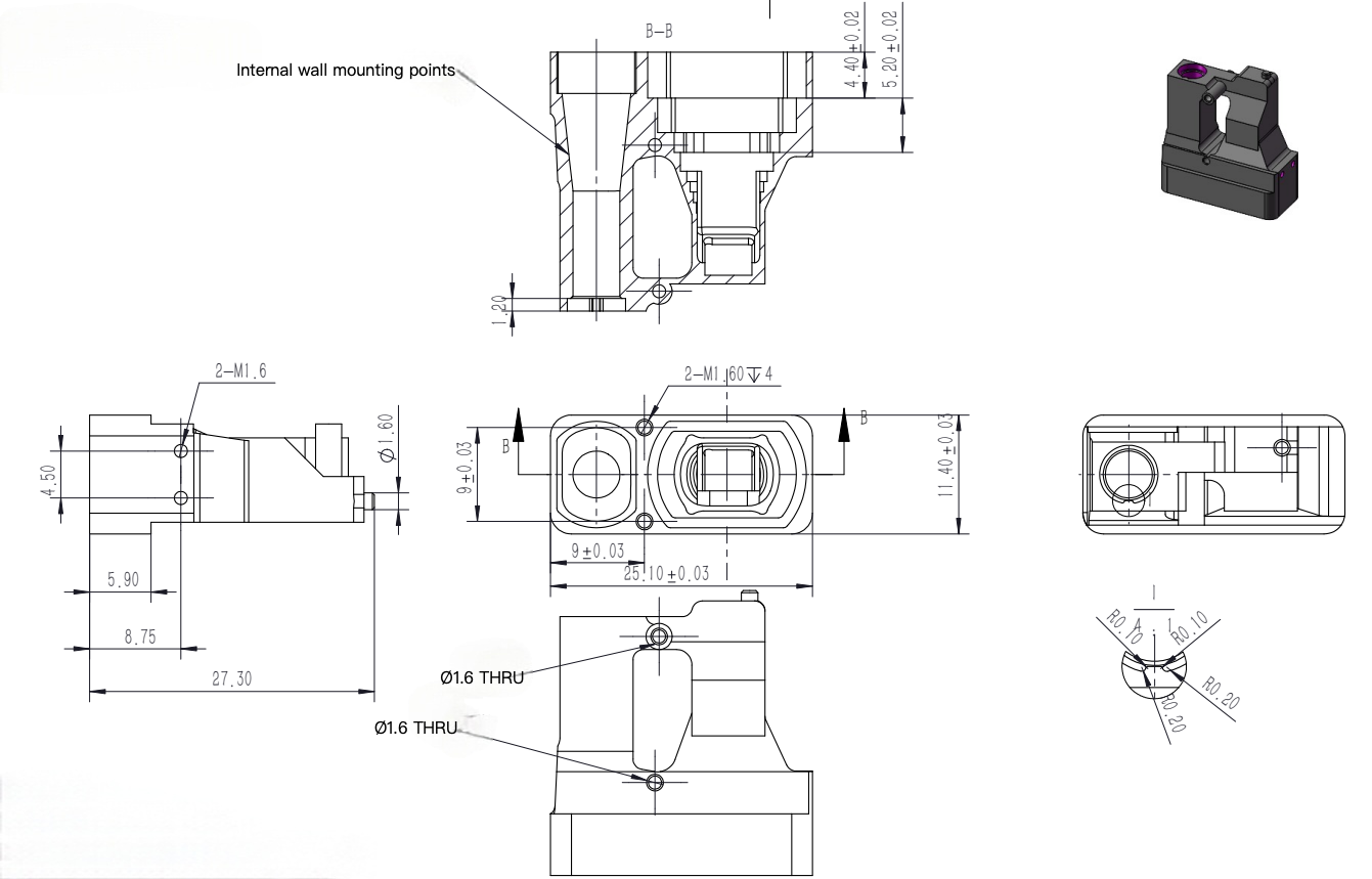 LRF3000A1 Mechanical DrawingManual page 5. Open the PDF to inspect the original dimensions and tolerances.