The technical material below is retained for this model only. Do not transfer a range, pulse, interface, mechanical or safety value from another 1535 nm product.
Specifications
LRF1525C is a 1535 nm pulsed distance-measurement module. Its assigned laser source is ER300; receiver-component data below come from the supplied APD-A13B001 R01 document. The three specification levels describe different assemblies and measurement conditions.
1. LRF1525C module specifications
Source clarifications
The source J30J interface table labels two supply contacts “VCC 5V” but describes their function as “12V Input Positive”. The conflicting source labels are retained for traceability, not as wiring instructions. Use the confirmed connector record supplied with the ordered unit.
LRF1525C — TECHNICAL SPECIFICATIONS
| Project |
Performance Indicators |
| Model |
LRF1525C |
| Laser Wavelength |
1.54μm±0.02μm |
| Module laser-safety statement |
Class I stated in the module document. Final accessible-emission classification applies to the complete configuration. |
| Divergence Angle |
≤0.3 mrad |
| Laser Energy |
≥500 μJ |
| Launch Lens Diameter |
Φ15 mm |
| Receiver Lens Diameter |
Φ50 mm |
| Measuring Range
(Reflectance 30%; visibility ≥ 18 km.)
|
4m×6m Objective ≥15 km |
| Minimum Range |
≤50 m |
| Ranging Frequency |
0.5Hz ~10Hz |
| Communication interface |
RS422 |
| Ranging Accuracy |
±2 m |
| Range Resolution |
≤0.1m |
| Precision Rate |
≥98% |
| False Alarm Rate |
≤1% |
| Pin-in-lead package model |
J30J |
| Supply Voltage |
DC12 V |
| Standby power consumption |
≤1.2W |
| Average power consumption |
≤2 W |
| Peak Power Consumption |
≤3W |
| Weight |
≤400g |
| Dimension (L×W×H) |
125mm×85mm×58.5mm |
| Operating Temperature |
-40~+70 ℃ |
| Storage Temperature |
-55~+75 ℃ |
| Impact Resistance |
Meet the MIL-STD-810G testing standard |
| Vibration Resistance |
Meet the MIL-STD-810G testing standard |
LRF1525C — PIN INTERFACE
|
External plug-in XS3
|
Model:Molex51021-0500
|
Remark
|
|
1
|
TTL RX
|
3.3V
|
|
2
|
TTL TX
|
3.3V
|
|
3
|
CTRL
|
3.3V-5V power on, 0V power off
|
|
4
|
+12V
|
Power supply+
|
|
5
|
GND
|
Power supply-
|
LRF1525C — PIN INTERFACE
|
Pin
|
Definition
|
Function
|
Remarks
|
|
1
|
GND
|
Serial Port Ground
|
|
|
2
|
GND
|
12V Input Negative
|
|
|
3
|
GND
|
12V Input Negative
|
|
|
4
|
VCC 5V
|
12V Input Positive
|
|
|
5
|
VCC 5V
|
12V Input Positive
|
|
|
6
|
RS422 RX+
|
Serial Port Receive +
|
From the upper computer to the rangefinder
|
|
7
|
RS422 RX-
|
Serial Port Receive -
|
From the upper computer to the rangefinder
|
|
8
|
RS422 TX-
|
Serial Port Transmit -
|
From the rangefinder to the upper computer
|
|
9
|
RS422 TX+
|
Serial Port Transmit +
|
From the rangefinder to the upper computer
|
Model-specific mechanical and interface drawings
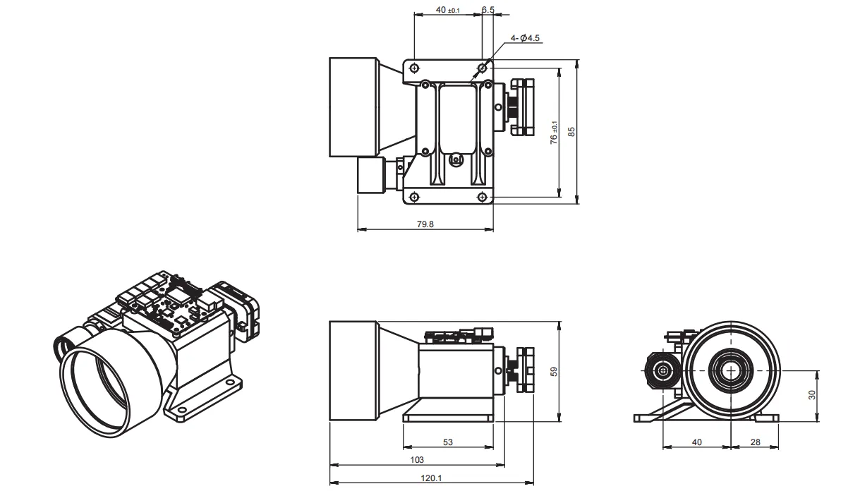
LRF1525C: OUTLINE DIMENSION(mm). Original model-bound drawing.
2. ER300 source-laser specifications
ER300 standalone laser component
| Parameter | Value |
| Optical wavelength |
1535 nm |
| Pulse energy |
≥300 µJ |
| Optical pulse width |
5 ns |
| Drive pulse width |
≤2.4 ms |
| Repetition rate |
1–10 Hz |
| Pulse stability |
10% (definition/statistical method not stated) |
| Raw beam diameter |
0.3 mm |
| Initial beam divergence |
≤7 mrad |
| Transverse mode |
TEM00 |
| Operating / storage temperature |
−40 to +65 °C / −55 to +75 °C |
| Package dimensions / mass |
25 × 8 × 6.8 mm / 8.5 g |
| Component electrical entry |
2 V, 12 A |
| Shock / vibration entries |
1500 G, 0.5 ms / 20–2000 Hz, 20 G |
| Stated service life |
>1 million shots; test conditions not supplied |
The electrical entries describe the component drive, not the module supply input. Drive conditions and pulse-width definitions must follow the component document and the individual factory record. An optical pulse-width value is not a pump-drive duration.
3. APD-A13B001 receiver-component specifications
Small screens: swipe the table horizontally to read all measurement conditions.
Supplied APD200 document — component values and conditions
| Parameter | Value | Measurement condition / scope |
| Device / active diameter |
APD-A13B001 R01 / 200 µm |
Supplied APD200 document, p1 |
| Detector spectral response interval |
800–1700 nm |
Detector response; not the filter passband |
| Responsivity |
0.9 A/W minimum; 1.0 A/W typical |
λ = 1550 nm; incident power = 1 µW; M = 1 |
| Dark current |
8 nA typical; 50 nA maximum |
VR = VBR − 3 V; incident power = 0 |
| Multiplication factor |
M ≥10 / M ≥30 |
λ = 1550 nm; 1 µW; respectively VBR − 3 V / VBR − 1 V |
| −3 dB bandwidth |
0.6 GHz minimum; 1.25 GHz typical |
M = 10; RL = 50 Ω |
| Breakdown voltage |
35–50 V |
Reverse current = 10 µA; incident power = 0 |
| Capacitance |
1.8 pF typical; 2.0 pF maximum |
VR = VBR − 3 V; f = 1 MHz |
| Breakdown temperature coefficient |
0.05 minimum / 0.11 typical / 0.15 maximum V/°C |
Reverse current = 10 µA; dark; −55 to +85 °C |
| Operating / storage temperature |
−40 to +85 °C / −55 to +125 °C |
Component absolute-maximum table; not module environmental ratings |
| Maximum bias |
VBR |
Absolute maximum, not a recommended operating setpoint |
| Maximum forward / reverse current |
5 mA / 3 mA |
Absolute maximum ratings, not continuous design targets |
| Filter centre wavelength |
1535 ±5 nm |
Supplied filter table, p3 |
| Filter FWHM |
<37 nm |
Full width at half maximum |
| Transmission at centre wavelength |
>90% |
Filter specification, not total receiver throughput |
| Blocking specification |
T <1%; source lists 400–1750 nm |
Stop-band/transition edges are not numerically defined; the stated blocking span is not a guarantee at every wavelength. |
| Optical surface quality |
60/40 |
Source label: surface quality; not a transmission value |