The technical material below is retained for this model only. Do not transfer a range, pulse, interface, mechanical or safety value from another 1064 nm product.
Specifications
The tables below retain the supplied model record except for entries explicitly withheld after a comparison with the current model PDF. A value, option or condition from another model is not interchangeable. General explanations are separated from model-specific entries.
Current LDR80K1 document — source checked 13 September 2026. On a small screen, swipe wide tables horizontally to read every column.
LDR80K1 — Technical Specifications
| Parameter | Specification |
| Wavelength |
1064 nm |
| Range (Ranging) |
≥ 10,000 m |
| Weight |
≤ 680 g |
| Dimensions |
116 mm × 52 mm × 96 mm |
LDR80K1 — TECHNICAL SPECIFICATIONS
|
Operating modes
|
Ranging and laser designation
|
|
Pump source
|
Laser diode array
|
|
Operating wavelength
|
1.064 μm
|
|
Average energy per designation cycle
|
Average single-pulse energy per designation cycle ≥ 80 mJ
|
|
Pulse energy fluctuation
|
Within one designation cycle, the single-pulse energy variation shall not exceed 10% of the average energy (over the full temperature range, with statistics taken 2 s after laser emission starts).
|
|
Beam divergence
|
≤ 0.30 mrad
|
|
Pulse width
|
15 ns ± 5 ns
|
|
Optical axis parallelism error
|
Parallelism error between the optical axis and the mounting reference: ≤ 0.5 mrad.
|
|
Ranging performance
|
- Minimum measuring distance: ≤ 300 m
- Maximum measuring distance: ≥ 10 km(for a 2.3 m × 2.3 m target with diffuse reflectance ≥ 0.2, visibility ≥ 23 km, and relative humidity ≤ 70%)
- Ranging rates: 1 Hz, 5 Hz, single-shot
- Ranging accuracy: ≤ 5 m
- Probability of correct ranging: ≥ 98%
- Continuous ranging operating time: 5 min(At 5 Hz: continuous operation for 5 min, rest time ≤ 3 min, then ranging can be continued.)
|
|
Laser designation performance
|
- Nominal designation repetition rate (for verification): 20 pps
- Short designation mode: each cycle has 17 s of designation time and 30 s interval; up to 8 consecutive cycles
- Long designation mode: each cycle has 60 s of designation time and 45 s interval; up to 4 consecutive cycles
- After completing one long and one short designation cycle, the interval before the next designation shall be within 30 minutes.
|
|
Laser coding
|
- Meets the weapon system coding requirements and provides user-programmable code expansion capability.
- Supports external synchronization input; the external signal can control the laser emission pattern for coding.
- Coding method: precise frequency code (eight groups of pre-stored period-code patterns).
- Coding accuracy: ≤ 2.5 μs.
|
|
Dimensions
|
≤ 116 mm × 52 mm × 96 mm
|
|
Weight
|
≤ 680 g
|
|
Electrical characteristics
|
- Input voltage: DC 18 V to 32 V
- The electrical and electronic components inside the laser rangefinder/designator are compatible with the system power characteristics.
- Average power: ≤ 80 W; peak power: ≤ 120 W
- After PCB design and debugging are completed, all circuit boards are coated with conformal coating to provide moisture, salt-spray and fungus protection.
|
|
External power input requirements
|
- When sharing the same power supply with motor or other inductive loads, the laser rangefinder/designator should use a soft-start (3–5 s). At the instant of sudden power-on, the induced voltage generated by motors and other inductive loads at the module input may be several times the nominal input voltage, which can cause over-voltage damage.
- During power-up, it is recommended to use the dedicated power-on control function of the laser rangefinder/designator to stagger its power-on time from other loads. After other loads have powered up and stabilized, then enable power to the rangefinder/designator.
- The power input of the laser rangefinder/designator should be isolated from other inductive loads. If conditions allow, a DC filter (30 V / 10 A) can be added at the module’s power input.
- The power supply for the laser rangefinder/designator shall satisfy the peak power demand. When testing the module alone, with a DC supply voltage of 24 V, the supply current should be greater than 6 A. If the output voltage is lower, the rated output current of the supply should be increased accordingly.
|
|
Temperature Requirements
|
High-Temperature Requirements
- Operating temperature: ≤ +55 °C
- Storage temperature: ≤ +65 °C
Low-Temperature Requirements
- Operating temperature: ≥ −40 °C
- Storage temperature: ≥ −45 °C
|
|
Vibration Requirements
|
The equipment shall withstand flight-induced vibration and shocks occurring during takeoff and landing. All components shall also meet the environmental conditions of vehicle transport.
Vibration spectrum:
- From 15 Hz to 33 Hz, constant-displacement sinusoidal vibration with amplitude 0.91 mm;
- From 33 Hz to 700 Hz, constant-acceleration sinusoidal vibration with amplitude 2 g.
Duration: 1 hour per axis in three orthogonal directions (X, Y, Z).
Test conditions:
The product shall be mounted on the vibration platform in its normal operating configuration and powered on during testing.
After vibration testing, the equipment shall operate normally.
|
|
Shock Requirements
|
- Vertical axis: ≥ 10 g
- Lateral axis: ≥ 10 g
- Longitudinal axis: ≥ 10 g
- Shock waveform: post-peak sawtooth, duration 11 ms; applied along X, Y, and Z axes, both directions on each axis, 18 shocks in total.
- Test conditions:
The product shall be mounted on the shock test platform in its normal operating configuration and powered on during testing.
After shock testing, the equipment shall operate normally.
|
LDR80K1 — Electrical Interface
|
Pin No.
|
Signal Definition
|
Input/Output
|
Description
|
Remarks
|
|
1.
|
+28V
|
Input
|
The power supply characteristics comply with the relevant requirements of MIL-STD-810G.
|
Power Supply
|
|
2.
|
+28V
|
|
3.
|
+28V
|
|
4.
|
+28V_GND
|
|
5.
|
+28V_GND
|
|
6.
|
+28V_GND
|
|
7.
|
Power-On Control (+)
|
Input/Output
|
Refer to the requirements specified in the Power-On Control section.
|
I/O Control
|
|
8.
|
Power-On Control (-)
|
|
9.
|
RS422_RX+
|
Input/Output
|
The logic level and drive capability comply with the RS-422 interface standard.
Characteristic impedance: 120 Ω.
|
The transmit/receive pin definitions correspond to the laser rangefinder itself.
|
|
10.
|
RS422_RX-
|
|
11.
|
RS422_TX+
|
|
12.
|
RS422_TX-
|
|
13.
|
RS422_GND
|
|
14.
|
External Synchronization Control Signal
|
Input
|
The logic level and drive capability comply with the RS-422 interface standard.
|
External synchronization signal used to control laser coding.
|
|
15.
|
External Synchronization Control Signal (–)
|
Technical drawings
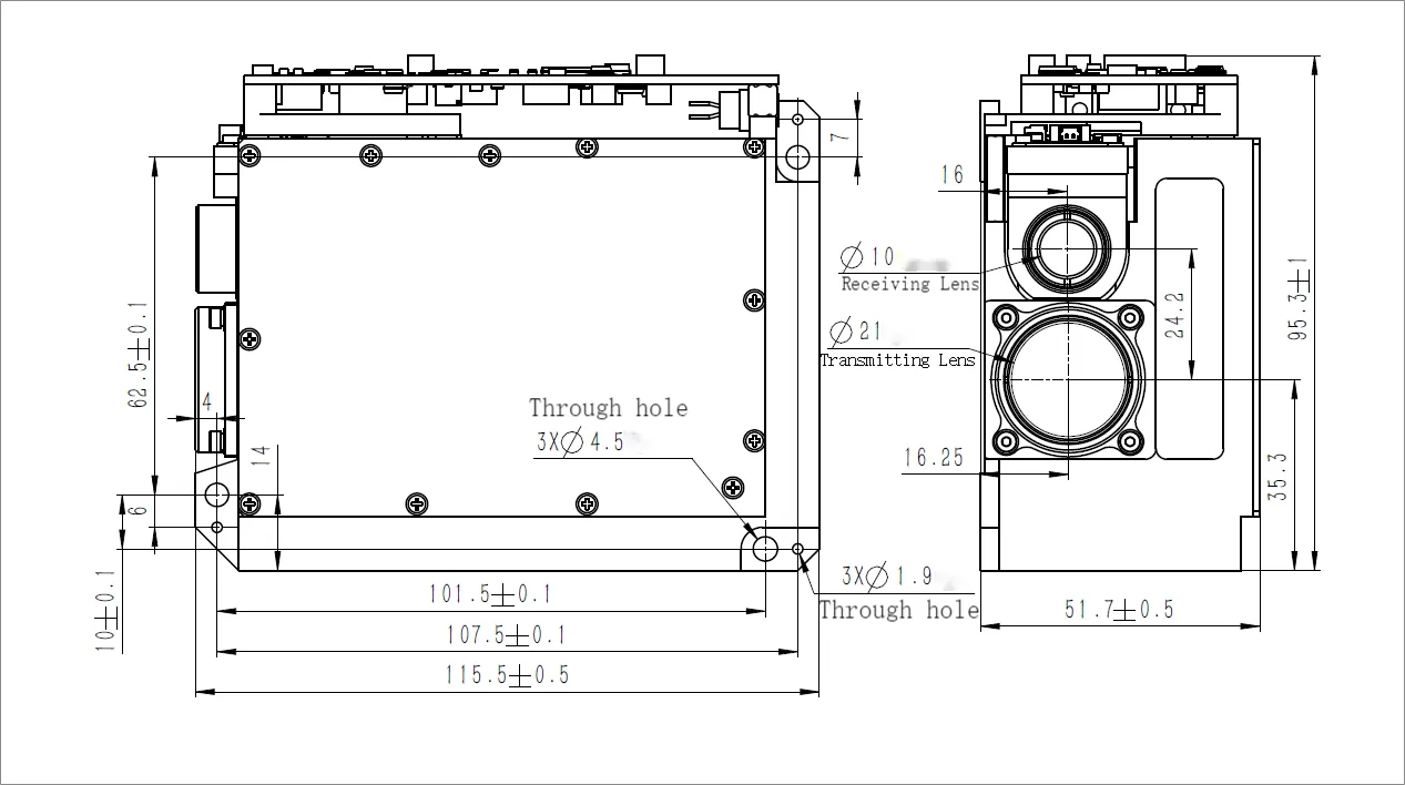
LDR80K1 — OUTLINE DIMENSION(mm)