The technical material below is retained for this model only. Do not transfer a range, pulse, interface, mechanical or safety value from another 1535 nm product.
Specifications
LRF0818C is a 1535 nm pulsed distance-measurement module. Its assigned laser source is ER300; receiver-component data below come from the supplied APD-A13B001 R01 document. The three specification levels describe different assemblies and measurement conditions.
1. LRF0818C module specifications
Source clarifications
The 4,500 m human-size and 2,600 m small-object entries are labelled “design guarantee” in the PDF. They must not be presented as measured field-test results.
LRF0818C — Technical Summary
|
Parameter
|
Specification
|
|
Operating wavelength
|
1535 nm ± 10 nm
|
| Laser-safety description |
The source describes the module as 1535 nm eye-safe but does not state a numerical laser class in the reviewed specification. Wavelength alone is not a classification. |
|
Transmitting aperture
|
Φ12 mm
|
|
Receiving aperture
|
Φ26 mm
|
|
Maximum range
Under visibility ≥ 12 km and relative humidity ≤ 60%, tested against a 0.3-reflectivity panel (or equivalent target)
|
Vehicle (2.3 m × 4.6 m): ≥ 8000 m
Human (0.5 m × 1.7 m): ≥ 4500 m (design guarantee)
Small object (0.2 m × 0.3 m): ≥ 2600 m (design guarantee)
|
|
Minimum range
|
≤ 20 m
|
|
Range accuracy
|
≤ ±2 m
|
|
Ranging rate
|
Single shot, 1 Hz, 2 Hz, 3 Hz, 4 Hz, 5 Hz, 10 Hz
|
|
Beam divergence
|
≤ 0.4 mrad
|
|
Operating temperature
|
−40 °C to +60 °C
|
|
Storage temperature
|
−50 °C to +70 °C (to be qualified at the system level)
|
|
Vibration
|
5→50→5 Hz sweep, 1 octave/min, 2.5 g (system-level qualification)
|
|
Shock
|
1200 g, 1 ms (system-level qualification)
|
|
Overall dimensions
|
≤ 59.5 mm × 26 mm × 32 mm
|
|
Weight
|
≤ 65 g
|
|
Communication interface
|
TTL
|
|
Supply voltage
|
4.5 V–16 V
|
|
Power consumption
|
Standby ≤ 1 mW;
Operating ≤ 4 W;
Peak ≤ 14 W @ 12 V
|
LRF0818C — additional source entries, PDF page 1
| Parameter | Value |
| Valid-return rate |
≥98% (module PDF statement) |
| Documented functions |
Single/continuous ranging; first/last return selection; range gate; built-in self-test; status and temperature reporting; shot counter; serial firmware update. These names do not disclose the implemented detection algorithm. |
LRF0818C — Electrical Interface
|
Pin #
|
Pin No.
|
Remarks
|
|
P-1
|
VIN+
|
Power input, 4.5–16 V
|
|
P-2
|
VIN-
|
Power ground (GND)
|
|
P-3
|
POWER_ON
|
Module power enable (TTL, 3.3 V logic level);
Module ON (> 2.7 V), module OFF (< 0.3 V)
|
|
P-4
|
UART_TX
|
UART TXD (serial transmit), TTL, 3.3 V logic level
|
|
P-5
|
UART_RX
|
UART RXD (serial receive), TTL, 3.3 V logic level
|
|
P-6
|
GND
|
Serial ground (SGND)
|
Model-specific mechanical and interface drawings
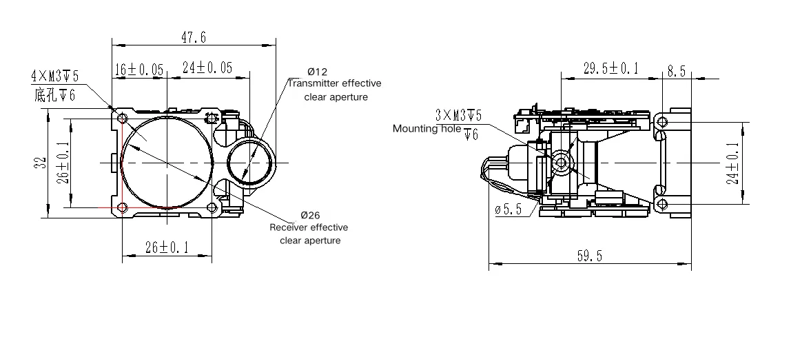
LRF0818C: Structural dimensions. Original model-bound drawing.
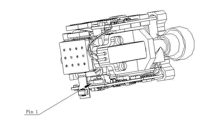
LRF0818C: Electrical Interface. Original model-bound drawing.
2. ER300 source-laser specifications
ER300 standalone laser component
| Parameter | Value |
| Optical wavelength |
1535 nm |
| Pulse energy |
≥300 µJ |
| Optical pulse width |
5 ns |
| Drive pulse width |
≤2.4 ms |
| Repetition rate |
1–10 Hz |
| Pulse stability |
10% (definition/statistical method not stated) |
| Raw beam diameter |
0.3 mm |
| Initial beam divergence |
≤7 mrad |
| Transverse mode |
TEM00 |
| Operating / storage temperature |
−40 to +65 °C / −55 to +75 °C |
| Package dimensions / mass |
25 × 8 × 6.8 mm / 8.5 g |
| Component electrical entry |
2 V, 12 A |
| Shock / vibration entries |
1500 G, 0.5 ms / 20–2000 Hz, 20 G |
| Stated service life |
>1 million shots; test conditions not supplied |
The electrical entries describe the component drive, not the module supply input. Drive conditions and pulse-width definitions must follow the component document and the individual factory record. An optical pulse-width value is not a pump-drive duration.
3. APD-A13B001 receiver-component specifications
Small screens: swipe the table horizontally to read all measurement conditions.
Supplied APD200 document — component values and conditions
| Parameter | Value | Measurement condition / scope |
| Device / active diameter |
APD-A13B001 R01 / 200 µm |
Supplied APD200 document, p1 |
| Detector spectral response interval |
800–1700 nm |
Detector response; not the filter passband |
| Responsivity |
0.9 A/W minimum; 1.0 A/W typical |
λ = 1550 nm; incident power = 1 µW; M = 1 |
| Dark current |
8 nA typical; 50 nA maximum |
VR = VBR − 3 V; incident power = 0 |
| Multiplication factor |
M ≥10 / M ≥30 |
λ = 1550 nm; 1 µW; respectively VBR − 3 V / VBR − 1 V |
| −3 dB bandwidth |
0.6 GHz minimum; 1.25 GHz typical |
M = 10; RL = 50 Ω |
| Breakdown voltage |
35–50 V |
Reverse current = 10 µA; incident power = 0 |
| Capacitance |
1.8 pF typical; 2.0 pF maximum |
VR = VBR − 3 V; f = 1 MHz |
| Breakdown temperature coefficient |
0.05 minimum / 0.11 typical / 0.15 maximum V/°C |
Reverse current = 10 µA; dark; −55 to +85 °C |
| Operating / storage temperature |
−40 to +85 °C / −55 to +125 °C |
Component absolute-maximum table; not module environmental ratings |
| Maximum bias |
VBR |
Absolute maximum, not a recommended operating setpoint |
| Maximum forward / reverse current |
5 mA / 3 mA |
Absolute maximum ratings, not continuous design targets |
| Filter centre wavelength |
1535 ±5 nm |
Supplied filter table, p3 |
| Filter FWHM |
<37 nm |
Full width at half maximum |
| Transmission at centre wavelength |
>90% |
Filter specification, not total receiver throughput |
| Blocking specification |
T <1%; source lists 400–1750 nm |
Stop-band/transition edges are not numerically defined; the stated blocking span is not a guarantee at every wavelength. |
| Optical surface quality |
60/40 |
Source label: surface quality; not a transmission value |