Meet the LR2000E4
The LR2000E4 is a compact ranging module in the E4 mechanical format. It provides digital distance measurements for equipment that needs a ranging subsystem rather than a standalone handheld meter.
Its standard measurement range is 4–2000 m. For distances above 400 m, the accuracy table uses a distance-dependent term of 0.4% of D. Use the model-specific accuracy formula when setting your system requirements.
The UART-TTL interface supports host-controlled measurements. The manual includes test-software guidance, a six-pin interface definition, and a hexadecimal communication protocol. Use the E4 drawing for packaging and mounting; an E2 drawing is not an interchangeable mechanical reference.
01
2000 m range class
4–2000 m standard range with a model-specific long-distance accuracy formula.
02
Host-controlled ranging
2–10 Hz (adaptive); single-shot and continuous measurement modes.
03
Compact integration
25.7 × 14.2 × 26.2 mm nominal dimensions in the current mechanical drawing; detailed tolerances remain controlling.
04
UART-TTL interface
115200 bps communication and a 3.3–5 V supply range; use the model-specific pinout and command table.
TECHNICAL DATA
LR2000E4 Specifications
Read performance values with their target and test conditions. The linked user manual provides the complete mechanical, electrical, and communication details.
| Parameter | Value | Conditions / notes |
| Laser wavelength |
905 ± 5 nm |
— |
| Measurement range |
4–2000 m |
Standard range; actual reach depends on target and environment. |
| Ranging accuracy |
±1 m (D ≤ 400 m); 0.4% of D (400 m < D ≤ 2000 m) |
Target reflectivity and size are not specified in the accuracy table. |
| Measurement update rate |
2–10 Hz (adaptive) |
Completed distance outputs; not the optical pulse-repetition rate. |
| Communication interface |
UART-TTL |
Custom configurations are specified separately. |
| Baud rate |
115200 bps |
— |
| Supply voltage |
3.3–5 V |
— |
| Operating temperature |
−20 °C to +60 °C |
— |
| Storage temperature |
−40 °C to +60 °C |
— |
| Mechanical drawing dimensions |
25.7 × 14.2 × 26.2 mm |
Drawing nominal values. Observe the individual tolerances in the model drawing; do not machine from the rounded summary alone. |
| Laser safety class |
Class 1 |
As stated in the model manual; finished-equipment assessment is separate. |
| Laser beam divergence |
< 6 mrad |
— |
| Optical material |
PMMA |
— |
| Receiver aperture |
9.2 mm × 14.5 mm |
— |
| Startup time |
≤ 200 ms |
— |
| Inrush current |
< 400 mA |
— |
| Operating power consumption |
≈ 1.2 W |
Approximate value in the specification table. |
- For civilian equipment only. The model manual prohibits military applications.
Operation and Data Output
Single-shot mode requests one reported distance. For a weak return, the manual describes repeated internal measurements before reporting stable distance data. Continuous mode produces repeated results at the documented adaptive update rate.
The standard measurement-rate specification is 2–10 Hz (adaptive). Use the current protocol table for command timing and output format.
Electrical Interface
| Pin | Signal | Function |
| 1 |
GND |
Power ground |
| 2 |
VCC |
Power input |
| 3 |
I/O (Reserved) |
Reserved for expansion |
| 4 |
TXD |
Transmit data: module → host |
| 5 |
RXD |
Receive data: host → module |
| 6 |
SW-SHOT |
Function-enable input. The required control polarity must match the supplied configuration. |
Mechanical Dimensions
Use the drawing and its tolerances for installation. This drawing is reproduced directly from the current LR2000E4 user manual.
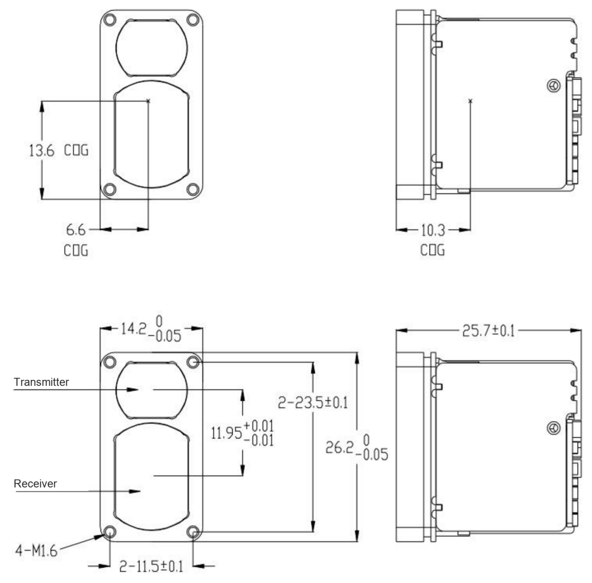 LR2000E4 Mechanical DrawingManual page 4. Open the PDF to inspect the original dimensions and tolerances.