The technical material below is retained for this model only. Do not transfer a range, pulse, interface, mechanical or safety value from another 1064 nm product.
Specifications
The tables below retain the supplied model record except for entries explicitly withheld after a comparison with the current model PDF. A value, option or condition from another model is not interchangeable. General explanations are separated from model-specific entries.
Source-review note
The source has an incomplete energy unit, time units under a frequency label, differing capability statements and conflicting shock-waveform labels. No missing unit, conversion or qualification outcome is inferred.
Current LDR80K2 document — source checked 13 September 2026. On a small screen, swipe wide tables horizontally to read every column.
LDR80K2 — TECHNICAL SPECIFICATIONS
|
Laser Wavelength
|
1064nm±1nm
|
|
Pump Mode
|
Side-pumped semiconductor (diode) pumping
|
| Designation Frequency |
Withheld pending a corrected, controlled model specification. See the source-review note above. |
|
Trigger Mode
|
Internal-Synchronization Illumination / External-Synchronization Illumination
(Trigger Delay: 304.0 μs ± 0.1 μs)
|
| Output Energy |
Withheld pending a corrected, controlled model specification. See the source-review note above. |
|
Dimensions
|
≤150×102×55mm
|
|
Weight
|
≤850g
|
| Designation Capability |
Withheld pending a corrected, controlled model specification. See the source-review note above. |
|
Q-Switch Type
|
Electro-optic Q-switch (EO Q-switch)
|
|
Pulse Width
|
15ns ±5ns
|
|
Beam Divergence
|
≤0.15mrad
|
|
Energy Instability
|
≤8%(RMS)
|
|
Laser Designation Performance
|
Short-duration irradiation mode: The irradiation time for each cycle is 17 seconds, followed by a 30-second interval. The system can perform up to 8 consecutive irradiation cycles.
Long-duration irradiation mode: The irradiation time for each cycle is 60 seconds, followed by a 45-second interval. The system can perform up to 4 consecutive irradiation cycles.
|
|
Optical Axis Parallelism Error Relative to Mounting Datum
|
≤0.5mrad
|
|
Ranging Performance
|
· Minimum Measuring Distance: ≤ 300 m
· Maximum Measuring Distance: ≥ 15 km
(under conditions of a 2.3 m × 2.3 m target, diffuse reflectivity ≥ 0.2, visibility ≥ 20 km, and relative humidity ≤ 70%)
· Ranging Frequency: 1–20 Hz (up to 3 simultaneous targets)
· Ranging Accuracy: ≤ 5 m
· Probability of Valid Ranging: ≥ 98%
· Continuous Ranging Operating Time: 90 s
(20 Hz continuous operation for 90 s, rest time ≤ 5 minutes before continuing ranging)
|
|
Communication Serial Interface
|
RS422
|
|
External Synchronization Interface
|
+5 V differential line driver/receiver, RS-422 interface (delay from external synchronization signal to laser emission: 304.0 μs ± 0.1 μs).
|
|
Laser Coding Mode
|
l Precise Frequency Coding
l Time Coding
l Pseudo-Random Coding
|
|
Period Accuracy
|
<+-1us
|
|
Power Supply
|
DC 20V ~ 28V
|
|
Power Consumption
|
During operation, the average power consumption is not more than 55W, and the peak power consumption is not more than 100W.
|
|
Low-Temperature Test
|
Operating temperature: −40 °C
Storage temperature: −45 °C
|
|
High-Temperature Test
|
Operating temperature: +60 °C
Storage temperature: +65 °C
|
|
Damp-Heat Test
|
Relative humidity: 95% ± 3%
Temperature: +35 °C ± 2 °C
Storage duration: 72 h
|
| Shock Test |
Withheld pending a corrected, controlled model specification. See the source-review note above. |
|
Vibration
|
The equipment shall withstand flight vibration and the shocks occurring during takeoff and landing, and all components shall meet the environmental conditions of vehicle transportation.
The vibration profile is a swept-frequency spectrum:
l From 5 Hz to 16 Hz, constant-displacement sinusoidal vibration with an amplitude of 1.5 mm;
l From 16 Hz to 60 Hz, constant-acceleration sinusoidal vibration with an acceleration level of 1.5 g.
Each of the three axes shall be vibrated for 36 minutes.
Test condition:
The product shall be mounted on the vibration table in its normal operating configuration and powered on during the test.
Post-test requirement:
After vibration testing, the equipment shall operate normally.
|
LDR80K2 — PIN INTERFACE
| J30J-21ZKP |
| pinout |
functionality |
clarification |
orientations |
note |
| 1 |
TX+ |
RS422 + |
exports |
RS422 communication interface |
| 2 |
TX- |
RS422 send - |
exports |
|
| 3 |
RX+ |
RS422 Receive + |
importation |
|
| 4 |
RX- |
RS422 Receive - |
importation |
|
| 5 |
GND |
RS422 Ground |
GND |
|
| 6 |
EN+ |
power supply enable (computing) |
|
24V power supply enable switch |
| 7 |
EN- |
power supply enable (computing) |
|
|
| 8-13 |
|
unoccupied |
|
|
| 14 |
A |
External Synchronous Differential+ (A) |
importation |
A, B are the A and B outputs of the differential chip (RS422 chip) |
| 15 |
B |
External Synchronous Differential - (B) |
importation |
|
| 16 |
LED+ |
DC5V |
importation |
Indicator light power supply |
| 17 |
LED- |
GND |
importation |
|
| 18-21 |
|
|
|
|
LDR80K2 — PIN INTERFACE
| J30J-04ZK |
| Pinout |
functionality |
clarification |
orientations |
note |
| A, B |
24V |
Power supply |
importation |
bonus |
| C, D |
GND |
electric place |
importation |
(loanword) hack (computing) |
Technical drawings
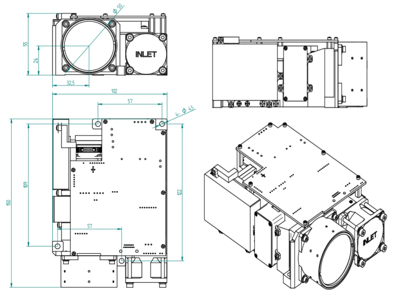
LDR80K2 — OUTLINE DIMENSION(mm)